@RuiMadureira - In regards to your original issue, we’ve identified the problem.
In the sample AutoCAD file you sent us, one of the lines on the pipe centerline layer was too small to be converted to a Revit pipe.
Revit min length: 0.31250 feet
CAD line length: 0.00003 feet
We fixed the issue by adding some code that will just ‘skip’ any lines that are too small.
We’ll work on building an updated Helix installer, and I’ll make a post in this thread once it’s ready for download. In the meantime, you might be able to get that AutoCAD file to work with the current Helix version by first removing any tiny lines in AutoCAD, and then trying the Helix tool again in Revit. The AutoCAD command ‘OVERKILL’ could come in handy for this task.
Here are two gifs, the first is a 2+ minute gif of me using the updated Helix code on the “M-Pipe-Std-Clin” layer of the sample .dwg file you shared with us. The second is of the CAD files and pipes in Revit after the process is finished. All in all, Helix converted about 2,700 lines into 786 Revit pipes in just over 2 minutes.
Blockquote
Hi Daniel.
Tested today with an single pipe and Revit gets this warning (picture attached).
Any guesses?
Regards.
@RuiMadureira - As for this issue, I’m not 100% sure as I’m not an experienced MEP Revit user, but I think the Revit error is because for whatever type of pipe you are mapping to that layer (you’ll see the type when you click on the ‘Family Type’ box in the Helix window in your screenshot), that type may not have a set ‘Pipe Segment’ inside that type’s routing preferences. It looks like you may be doing this test inside a new empty model, which if not from the correct template may not have the Routing Preferences set yet. See the below screenshot to see how to access the Routing Preferences window after having a pipe from your model selected.
Hi @Daniel !
Thank you very much for your support and help!
Infornutaly i am missing something in my process, guided by your explanation.
Could you please help me with more details?
I specified the thickness of lines in Autocad, don’t now how to use “OVERKILL” command and even so the result was like the image i attach without any pipes creation
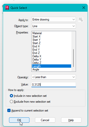
My AutoCAD knowledge is a little rusty so forgive me, but I think a better way than OVERKILL to remove short lines may be to use QSEL (Quick Select). I have it a try, and it worked for me with the below settings. Note that my units are set to Decimal Feet, you may have to use a different Value if your .dwg file’s units are set to something else:
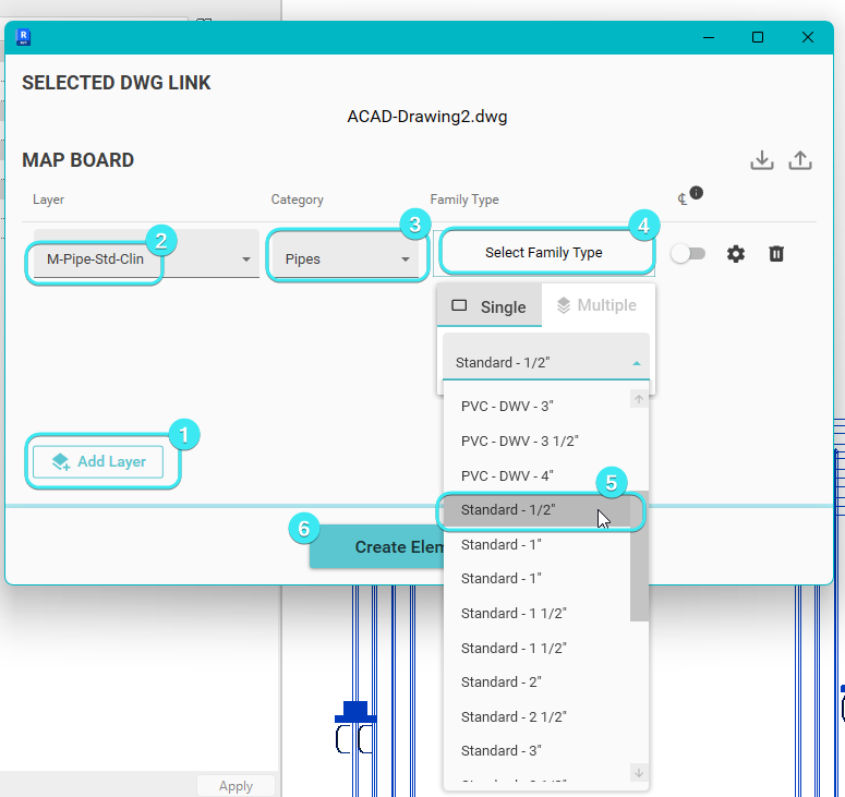
As for my process to convert the .dwg file into Revit Pipes, I created a new Revit project in Revit 2023 using the provided ‘New Imperial Systems’ template. I used the below settings, clicked ‘Create Elements’, and then waited a few minutes. To make the .gif, I also opened a ed view and hid the CAD link in that view so I could watch the progress as the pipes were created. In total, it took about 3 minutes, and I had to wait for Helix to finish (you get a little popup) so that I knew it was done.