No real requirement for how layers need to be setup, but you are limited to layer and the spacing between the parallel lines to determine the type it will map to.
If you have a lot of wall types that are similar widths, it may be difficult to differentiate between them without the lines being on different layers.
Did you configure a map to each layer that represent walls? If you share the mapping file that was configured, it should help get to the bottom of the issue.
One thing to note that Walls with hosted objects like Doors/Windows will be segments unless the hosted object is also mapped to bridge the gaps. Sometimes if these segments are short enough they will not be picked up.
Currently the walls are just created at a fixed height. It’s a bug that will be addressed. Development has been slower than we would like as we are a small team, it is on the radar though.
But if the CAD layers are clearly defined, like one for 300mm block and another for 300mm concrete, and we have Revit families mapped to them, why would it be difficult they have similar widths? The width is the same, but the layer tells us what it is.
Thanks for the update on the fixed height changes. This would be a welcome addition.
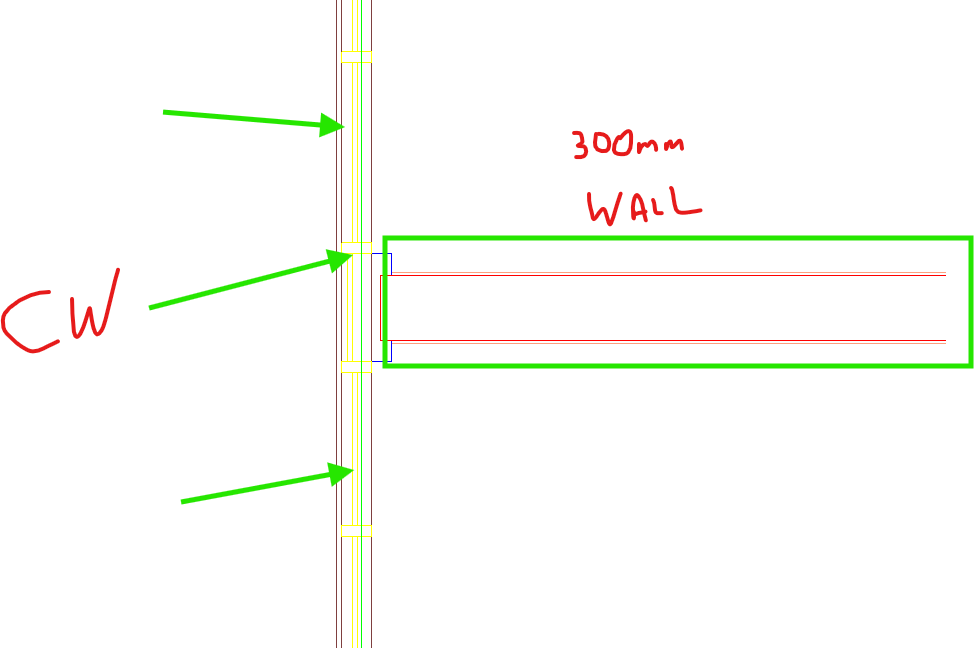
I think some of our issue is with how the CAD is set up. Esepcially the curtain wall. We just need 2 lines, not all the mullion outlines and panels. These are all the same layer. However, the initial issue remains, the main structural wall is simple 300mm thick, and when we apply a simple 300mm wall, it only applies it to some walls. Also, we have a gypsum layer on each side. Maybe we need to remove the extra lines, and have one overall thickness and apply a wall family with gypsum already applied. Back to my question, it seems like the CAD file needs a lot of set up for a complex model.
Sorry should have been clearer, I meant it would get dicey if you had same layer, similar width. Different layers should make it easy. A mapping for each layer pointing it at each type.
Regarding the 300mm wall, is the gyp and the core on the same layer just colored different? If the gyp is on a different layer, then you should be able to map the core layer. Then just map that layer to a Revit wall type that includes the gyp. Helix will place the path of the wall in the center between the two lines, any symmetrical walls this will work without issue. But if you had something on one side but not the other it would lead to inaccuracy.
On the CW, similarly if there is a layer that is the outside face only and it seems there may be in the screen shot (brownish color) you could target that specific layer to map and be what determines the path. Hoping the yellow mullions is just a draw order thing but this would get messy if the brownish layer is segmented at each mullion.
Regarding “CAD file needs a lot of set up for a complex model.” there may be ways to simplify a complex model mapping by using a strategy that uses more simple geometry.
If you want to connect over a call shoot me a PM, I can share over a calendar link to schedule some time to nerd out.